Breathing New Life: Building a Home Server from Old Laptop

Breathing New Life: Building a Home Server from Old Laptops

Breathing New Life: My DIY Home Server Project! 💻➡️🏠

Turning e-waste into a useful home lab with a bit of tinkering.

The Spark ✨: Old Laptops Get a Second Chance

Recently, a friend gifted me some old laptops. Instead of letting them gather dust or become e-waste, I saw an opportunity! 💡 Why not build a home server? It's a great way to learn, host services, and make use of hardware that might otherwise be discarded.

Old Laptop Case Another Old Laptop Case

The challenge? These laptops came barebones – no SSD, no RAM, and crucially, no power adapter! But where there's a will (and some spare parts), there's a way.

The Hardware Hustle 🛠️: Powering Up!

The biggest hurdle was power. Luckily, I had a nifty USB-C PD Fast Charger Decoy Board (100W capable!) lying around. These little boards can negotiate specific voltages from USB-C Power Delivery chargers.

USB C PD Decoy Board

The laptop needed 19V via its barrel jack. I configured the decoy board's DIP switches to request 20V from my USB-C charger (close enough!). Then came the slightly nerve-wracking part: soldering! 👨‍🏭

  • Identified the positive (+) and ground (-) pins on the laptop's power input.
  • Soldered the decoy board's output wires directly to these points.
  • Carefully cut a small slot in the laptop's casing to neatly house the board.
  • Used strong double-sided tape to secure the board inside.
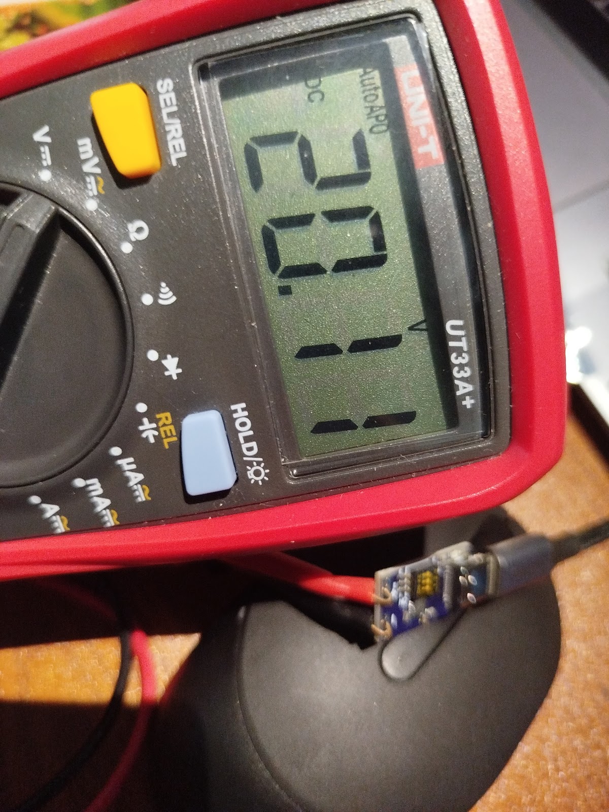
Soldering the PD board Laptop drawing power via USB C

Plugged in the USB-C charger, held my breath... and success! 🎉 The laptop powered on, drawing juice through the new setup. Phew!

Next, I installed some spare DDR3 RAM and an old SATA SSD I had available. Hardware complete! ✅

The Software Stack 🐧🐳: Ubuntu & Docker

With the hardware sorted, it was time for the operating system. I opted for Ubuntu Server – it's stable, widely supported, and great for server tasks. Installation was straightforward via a USB drive.

Installing Ubuntu Server

To manage the various services I wanted to run, I decided to use Docker. Containers make it super easy to install, run, and manage applications in isolated environments. No more dependency nightmares! 🐳

Installing Docker on Ubuntu:

# Update package list
sudo apt update

# Install prerequisites
sudo apt install -y apt-transport-https ca-certificates curl software-properties-common

# Add Docker's official GPG key
curl -fsSL https://download.docker.com/linux/ubuntu/gpg | sudo gpg --dearmor -o /usr/share/keyrings/docker-archive-keyring.gpg

# Add Docker repository
echo "deb [arch=$(dpkg --print-architecture) signed-by=/usr/share/keyrings/docker-archive-keyring.gpg] https://download.docker.com/linux/ubuntu $(lsb_release -cs) stable" | sudo tee /etc/apt/sources.list.d/docker.list > /dev/null

# Install Docker Engine
sudo apt update
sudo apt install -y docker-ce docker-ce-cli containerd.io

# Add your user to the docker group (to run docker without sudo - log out/in after)
sudo usermod -aG docker ${USER}

# Verify installation
docker --version

Note: You'll need to log out and log back in for the group change (`usermod`) to take effect.

My Container Crew 🚀: Services Running

Here are the initial containers I set up:

🗄️ ArchiveBox (Good Karma Kit)
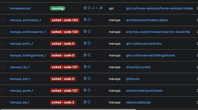
ArchiveBox Interface

This awesome tool creates local, browsable archives of websites. Perfect for saving articles, documentation, or anything important online before it disappears. The Good Karma Kit aspect seems focused on archiving public interest content.

Docker Run Command:

docker run -d \
  --name archivebox \
  -p 8000:8000 \
  -v ~/archivebox_data:/data \
  archivebox/archivebox

Access it at `http://[your-server-ip]:8000`. Replace `~/archivebox_data` with your desired host path for data storage.

🚢 Portainer

Crontab example

Managing Docker containers via the command line is fine, but Portainer provides a fantastic web UI. It makes it easy to view logs, manage containers, networks, volumes, and more. Highly recommended for managing your Docker environment!

Docker Run Command (Portainer CE):

# First, create a volume for Portainer data
docker volume create portainer_data

# Then, run the Portainer container
docker run -d \
  -p 8000:8000 \
  -p 9443:9443 \
  --name portainer \
  --restart=always \
  -v /var/run/docker.sock:/var/run/docker.sock \
  -v portainer_data:/data \
  portainer/portainer-ce:latest

Access it at `https://[your-server-ip]:9443` (HTTPS) or `http://[your-server-ip]:8000`. You'll set up an admin user on first access.

🎬 Plex Media Server

Portainer Dashboard

No home server is complete without a media solution! Plex organizes your movies, TV shows, music, and photos, allowing you to stream them to virtually any device, anywhere. It scans your media folders and automatically fetches metadata and artwork.

Docker Run Command (Requires Plex Claim Token):

# Get a claim token from https://www.plex.tv/claim/
# Replace YOUR_CLAIM_TOKEN, /path/to/plex/config, /path/to/tvshows, /path/to/movies

docker run -d \
  --name plex \
  --network=host \
  -e PLEX_UID=$(id -u) \
  -e PLEX_GID=$(id -g) \
  -e PLEX_CLAIM="YOUR_CLAIM_TOKEN" \
  -e TZ="Your/Timezone" `# e.g., Asia/Colombo` \
  -v /path/to/plex/config:/config \
  -v /path/to/transcode/temp:/transcode \
  -v /path/to/media/tvshows:/data/tvshows \
  -v /path/to/media/movies:/data/movies \
  --restart unless-stopped \
  plexinc/pms-docker:latest

Access the setup wizard at `http://[your-server-ip]:32400/web`. Make sure the paths you map (`/path/to/...`) exist on your host system and have correct permissions.

🏠 Home Assistant

Plex Interface

Home Assistant! It's an incredibly powerful open-source home automation platform. You can integrate smart devices, create automations, track sensors, and build amazing dashboards.

Docker Run Command:

docker run -d \
  --name homeassistant \
  --privileged \
  --restart=unless-stopped \
  -e TZ=Your/Timezone `# e.g., Asia/Colombo` \
  -v /path/to/homeassistant/config:/config \
  --network=host \
  ghcr.io/home-assistant/home-assistant:stable

Access it at `http://[your-server-ip]:8123`. Replace `/path/to/homeassistant/config` with your desired config path. `--network=host` is often needed for device discovery.

📊 btop++ (Resource Monitor)

While not typically run as a Docker container, `btop++` is an excellent TUI (Text User Interface) resource monitor. It gives a detailed, real-time view of CPU, memory, disk, and network usage right in your terminal. Very handy for seeing how the server is performing!

Installation Command (Ubuntu):

sudo apt update
sudo apt install -y btop

Usage:

btop

Smart Scheduling ⏰: Working Around Data Caps

My ISP offers unlimited data during off-peak hours (midnight to 7 AM). To take advantage of this for potentially data-intensive tasks (like ArchiveBox fetching sites), I set up a cron job. Cron is a time-based job scheduler in Unix-like operating systems.

I scheduled tasks to automatically stop certain containers at 7 AM and start them again at midnight. This helps manage bandwidth usage and costs effectively. 💰

Example Cron Job (Edit with `crontab -e`):

# Stop ArchiveBox container at 7:00 AM daily
0 7 * * * docker stop archivebox

# Start ArchiveBox container at 00:00 AM (midnight) daily
0 0 * * * docker start archivebox

You'd add similar lines for any other containers you want to schedule.

What's Next? 🤔 More Containers!

This is just the beginning! I'm excited to explore more self-hosted applications. What other containers do you recommend for a home server setup?

Some popular ideas include:

  • Nextcloud ☁️: Your own private cloud for files, calendars, contacts, and more (like Google Drive/Dropbox).
  • Pi-hole 🚫: Network-wide ad blocker. Say goodbye to most ads on all your devices!
  • Vaultwarden (Bitwarden server) 🔑: Self-hosted password manager.
  • Jellyfin 🎞️: Another excellent open-source media server alternative to Plex.
  • AdGuard Home 🛡️: Similar to Pi-hole, provides network-wide ad and tracker blocking.
  • Uptime Kuma 📈: A fancy monitoring tool to check if your services (and other websites) are online.

Let me know your favorite self-hosted apps!

Project built with spare parts, caffeine, and open-source software. ☕

Dumping firmware and resetting fuses of STM32 using OPENOCD and JTAG

Dumping STM32F105 Firmware on Ubuntu using ST-LINK
CAN bus filter board
MB_CAN_Filter Board

I recently got a CAN bus filter from AliExpress MB_CAN_FIlter. The existing firmware is used to bypass the Odometer of the premium cars like Mercedes, BMW by modifying the CAN signal that are passed through it. But we can utilize this for better endeavors like resetting the BMS signals of EVs to expand the lifetime of the battery and replacing batteries of higher capacity.

So it is essential to understand how this Circuit works, and learn the Basics of dumping the existing firmware and flashing new firmware to the Chip it is using.

The board here uses a STM32F105C8T6 Microcontroller and the CAN Transceivers ICs are some TJA1057. There is a similar board that uses the MCP2551.

There are multiple reasons why this board is wonderful as well as has many issues related to the PCB in which I will be going through maybe will opensource the designs in the future.

Dumping STM32F105 Firmware on Ubuntu using ST-LINK

This guide details how to install the required tools and dump the firmware from an STM32F105 microcontroller using an ST-LINK programmer on an Ubuntu system. We will cover two common tools: STM32CubeProgrammer (the official ST tool) and OpenOCD (an open-source alternative).

1. Prerequisites

  • Hardware:
    • STM32F105-based board (See Section 3 for a specific example).
    • ST-LINK V2 or V3 programmer/debugger.
    • USB cables for the ST-LINK and potentially the target board (if it needs separate power).
    • Jumper wires for SWD connection.
  • Software:
    • Ubuntu Linux (instructions tested on recent LTS versions like 20.04/22.04).
    • Internet connection for downloads.

2. Tool Installation

a) STM32CubeProgrammer

STM32CubeProgrammer is STMicroelectronics' official tool for programming STM32 devices. It replaces older tools like ST-LINK Utility and STM Flasher.

  1. Download: Go to the STMicroelectronics STM32CubeProgrammer page. Download the Linux version (usually a .zip file). You might need an ST account.
  2. Install Java: CubeProgrammer requires Java. Check if it's installed and install it if necessary:
    java -version
    # If not installed or version is too old:
    sudo apt update
    sudo apt install default-jre -y
  3. Extract: Unzip the downloaded file:
    unzip en.stm32cubeprg-lin_*.zip -d stm32cubeprogrammer
    cd stm32cubeprogrammer
  4. Run Installer: Execute the Linux installer script. You might need to make it executable first.
    chmod +x SetupSTM32CubeProgrammer*.linux
    sudo ./SetupSTM32CubeProgrammer*.linux
    # Or run without sudo for user-local installation if preferred
    # ./SetupSTM32CubeProgrammer*.linux
    Follow the on-screen installation steps. The default installation location is often /usr/local/STMicroelectronics/STM32Cube/STM32CubeProgrammer/.
  5. Add to PATH (Optional): To run the command-line interface (CLI) easily, add its directory to your PATH. Find the bin directory within your installation path (e.g., /usr/local/STMicroelectronics/STM32Cube/STM32CubeProgrammer/bin) and add it to your ~/.bashrc or ~/.zshrc:
    echo 'export PATH="$PATH:/usr/local/STMicroelectronics/STM32Cube/STM32CubeProgrammer/bin"' >> ~/.bashrc
    source ~/.bashrc
    Verify by running: STM32_Programmer_CLI --version

b) OpenOCD

Open On-Chip Debugger (OpenOCD) is a versatile open-source tool.

  1. Install: Use the package manager:
    sudo apt update
    sudo apt install openocd -y
  2. Verify: Check the installation:
    openocd --version

c) ST-LINK Udev Rules

To allow access to the ST-LINK device without needing sudo for every command:

  1. Create Rules File: Create a new udev rules file:
    sudo nano /etc/udev/rules.d/99-stlink.rules
  2. Add Rules: Paste the following content into the file. These rules cover various versions of ST-LINK.
    # ST-Link v1
    ATTRS{idVendor}=="0483", ATTRS{idProduct}=="3744", MODE="0666"
    # ST-Link v2
    ATTRS{idVendor}=="0483", ATTRS{idProduct}=="3748", MODE="0666"
    # ST-Link v2-1
    ATTRS{idVendor}=="0483", ATTRS{idProduct}=="374b", MODE="0666"
    # ST-Link v3
    ATTRS{idVendor}=="0483", ATTRS{idProduct}=="374f", MODE="0666"
    ATTRS{idVendor}=="0483", ATTRS{idProduct}=="3752", MODE="0666"
    ATTRS{idVendor}=="0483", ATTRS{idProduct}=="3753", MODE="0666"
  3. Save and Close: Press Ctrl+X, then Y, then Enter.
  4. Reload Rules: Apply the new rules:
    sudo udevadm control --reload-rules
    sudo udevadm trigger
  5. Reconnect: Unplug and replug your ST-LINK programmer.

3. Hardware Overview (User's Board Example)

This section describes the specific hardware components mentioned for the target board being used in this example.

  • Microcontroller: STM32F105C8T6
    • Rationale: This MCU from the STM32F1 series (Connectivity Line) is chosen primarily for its dual CAN interfaces (bxCAN), which is essential for applications requiring communication on two separate CAN buses (e.g., bridging, gateway). Additionally, many of its GPIO pins are 5V tolerant, which simplifies interfacing with 5V peripherals like some CAN transceivers, although direct connection still requires careful consideration of signal levels.
  • CAN Transceiver: TJA1057
    • Rationale: This is a high-speed CAN transceiver. Compared to other common options in the TJA10xx family (like the TJA1050), the TJA1057 often provides improved ElectroMagnetic Compatibility (EMC) and ElectroStatic Discharge (ESD) performance. It might also offer features like specific low-power modes or better behavior under bus fault conditions, making it a robust choice for CAN communication.
  • Voltage Regulators: AMS1117-3.3 (3.3V LDO) and AMS1117-5.0 (5V LDO)
    • Function: These are Linear Low-Dropout regulators used to provide stable 3.3V (for the MCU and potentially other logic) and 5V (likely for the CAN transceiver VCC or other peripherals) from a higher input voltage.

Potential Board Design Considerations/Issues:

  • LDO Inefficiency: Using AMS1117 LDOs, especially for significant voltage drops (e.g., 12V input down to 5V or 3.3V) or higher current demands, leads to power loss as heat. This can reduce overall efficiency and potentially require heatsinking. Switch-mode buck converters are generally more efficient but add complexity and potential noise. LDOs like the AMS1117 also require specific types and values of input/output capacitors for stability, which must be correctly implemented.
  • Non-Automotive Grade MCU: The STM32F105C8T6 is typically a commercial or industrial grade component. If the application is intended for automotive environments, using a non-automotive qualified MCU might pose risks regarding temperature range limitations, long-term reliability, and lack of specific automotive certifications (AEC-Q100).
  • Lack of Feedback LEDs: The absence of status LEDs (e.g., Power OK, CAN TX/RX activity, Heartbeat) makes visual debugging and diagnostics difficult. It's hard to tell if the board is powered correctly or if communication is active without external measurement tools.
  • Noise Reduction and EMI Protection: For reliable CAN communication, especially at high speeds or in noisy environments, careful PCB layout, proper CAN bus termination (e.g., 120-ohm resistors), common-mode chokes, and potentially transient voltage suppression (TVS) diodes are crucial. Lacking these can lead to communication errors or susceptibility to electromagnetic interference.

4. Connecting Hardware (ST-LINK SWD)

Connect the ST-LINK programmer to your STM32F105 board using the SWD interface:

  • ST-LINK SWDIO <--> Target SWDIO (often PA13)
  • ST-LINK SWCLK <--> Target SWCLK (often PA14)
  • ST-LINK GND <--> Target GND
  • ST-LINK VCC/VDD <--> Target VDD (usually 3.3V, ensure voltage matches the MCU's VDD)
  • (Optional but Recommended) ST-LINK NRST <--> Target NRST (Reset pin)

Ensure the target board is powered on (using its own power supply, likely regulated by the onboard AMS1117s).

5. Dumping Firmware

The STM32F105 typically has Flash memory starting at address 0x08000000. The size varies; the C8 variant usually has 64KB (0x10000 bytes), but the F105 line goes up to 256KB (0x40000 bytes). Verify the exact flash size for your STM32F105C8T6 (it's 64KB) and adjust the size parameter accordingly.

a) Using STM32CubeProgrammer CLI

  1. Connect and Verify:
    # Read device ID register
    STM32_Programmer_CLI -c port=SWD freq=4000 mode=NORMAL -r32 0xE0042000 1
    This command attempts to connect via SWD at 4MHz and read a device ID register. It should output some information about the connected device if successful.
  2. Read Flash to Binary File (for STM32F105C8T6 - 64KB):
    # Use 0x10000 for 64KB Flash size
    STM32_Programmer_CLI -c port=SWD freq=4000 mode=NORMAL -r 0x08000000 0x10000 firmware_dump.bin
    This reads 64KB (0x10000 bytes) starting from address 0x08000000 and saves it to firmware_dump.bin.
  3. Read Flash to Hex File (for STM32F105C8T6 - 64KB):
    STM32_Programmer_CLI -c port=SWD freq=4000 mode=NORMAL -r 0x08000000 0x10000 firmware_dump.hex
    This saves the firmware in Intel HEX format instead of raw binary.

b) Using OpenOCD

  1. Start OpenOCD: Open a terminal and run:
    # Use stlink-v2.cfg for ST-LINK V2, stlink.cfg often works for V2/V3
    # stm32f1x.cfg is the target configuration for the STM32F1 series
    openocd -f interface/stlink.cfg -f target/stm32f1x.cfg
    OpenOCD connection output
    OpenOCD connection output example
    OpenOCD will try to connect to the target. Look for output indicating successful connection and halting the target CPU. It should also detect the flash size (likely reporting 64k).
  2. Connect via Telnet: Open another terminal window and connect to the OpenOCD server (which listens on port 4444 by default):
    telnet localhost 4444
    Telnet connection to OpenOCD
    Telnet connection output
  3. Halt CPU (if not already halted):
    > halt
  4. Dump Firmware (for STM32F105C8T6 - 64KB): Use the dump_image command:
    # dump_image <filename> <address> <size>
    # Use 0x10000 for 64KB flash size
    > dump_image firmware_dump_openocd.bin 0x08000000 0x10000
    This command reads 64KB from flash address 0x08000000 and saves it to firmware_dump_openocd.bin in the directory where you launched OpenOCD.
  5. Exit Telnet: Type exit and press Enter.
  6. Shutdown OpenOCD: Go back to the first terminal (where OpenOCD is running) and press Ctrl+C to stop it.

6. Troubleshooting

  • Permission Denied / Cannot Open Device: Ensure udev rules are correctly set up and applied, or run the command using sudo (not recommended for regular use).
  • Cannot Connect / Target Not Found:
    • Double-check SWD wiring (SWDIO, SWCLK, GND, VDD).
    • Ensure the target board is powered correctly via its regulators.
    • Try lowering the SWD frequency (freq=1000 in CubeProgrammer, adapter speed 1000 in OpenOCD telnet session).
    • Try connecting under reset: Use mode=UR (Under Reset) in CubeProgrammer, or add connect_assert_srst to the OpenOCD command line before -f target/.... Ensure the NRST line is connected.
    • Check if the debug pins (SWDIO/SWCLK) have been disabled by the firmware. If so, connecting under reset might be the only option.
  • OpenOCD Errors: Pay attention to the specific error messages. Sometimes the wrong interface or target script is used. Ensure the detected flash size matches your expectation (64k for C8T6).

You now have the firmware dumped as a .bin or .hex file, which you can analyze or use as a backup.

Firmware dump progress 1
Firmware dump progress
Firmware dump progress 2
Firmware dump completion
Firmware dump verification
Dump verification

From each step it is possible to Dump the Firmware.

Using OpenOCD we can also reset the fuses that are used in the MCU, if you look at the code, I reset the fuses that had set the STM32 to read only mode. Doing so can reduce the effects of corruption of the firmware.

References

Turning My Roller Gate into a Smart WiFi-Controlled System

DIY WiFi Roller Gate Controller with ESP32-C3

ESP32C3 Board on Proto Board

Have you ever wondered if you could take any device and control it from your phone? Well, I did! I wanted to transform my home roller gate into a WiFi-controlled system, eliminating the unreliable RF remote provided by the manufacturer.

The Problem with Manufacturer-Provided Remotes

The RF remote that came with my roller gate has been a constant source of frustration:

  • Excessive Battery Drain: The remote’s battery runs out too quickly.
  • Lost Programming: The remote frequently forgets its paired state.
  • Manufacturer Dependency: If the remote malfunctions, I have to rely on the manufacturer to fix it.

To make things worse, the battery used in these remotes is:

  • Difficult to find in Sri Lanka
  • Toxic and disposable – A single-use battery with harmful compounds

Additionally, for some unknown reason, the system often loses its remote pairing, requiring reprogramming. While the controller board has a "Learn Mode", the manufacturer insists on doing the reprogramming themselves, which is both inconvenient and unnecessary.

And let’s not forget the cost—if you lose or damage a remote, replacing it costs over 3,000 rupees!

Time to Put My Electronics Degree to Work!

With all these issues piling up, I decided to take matters into my own hands. Using my background in electronics, I set out to build a WiFi-based solution that would allow me to control my roller gate from anywhere—no more unreliable remotes!

Soldered Prototype Board

Reverse Engineering the Gate Controller

Curious about how the gate controller worked, I decided to take apart the control board and see if I could integrate my own system. On the right side of the board, I found a green terminal block with markings for different functions:

  • UP
  • DOWN
  • STOP

Each pin was pulled up to 12V, meaning that shorting them to ground would activate the corresponding function. This was great news! It meant I could control the gate using simple transistors.

Designing the Circuit

To interface with the controller, I designed a simple circuit that allows an ESP32-C3 to switch these functions using three 2N3904 NPN transistors. Here's the schematic:


       +12V INPUT
           │
         [LM7805] (Voltage Regulator)
           │
           +5V ───────────────────+────────+
           │                      │        │
          GND                     │       GND (ESP32)
           │                      │        │
   .-------+----------------.     │        │
   |       │                |     │        │
   |     [ESP32-C3]         |     │        │
   |       │                |     │        │
   |   GPIOx ──[150Ω]─► B   |     │        │ Gate Controller Inputs
   |   GPIOy ──[150Ω]─► B   |     │        │ (Pulled up to +12V)
   |   GPIOz ──[150Ω]─► B   |     │        │
   '------------------------'     │        │
           │    │    │            │        │
           E    E    E            │        │
           │    │    │            │        │
         [2N3904] [2N3904] [2N3904] │        │
           │    │    │            │        │
           C    C    C            │        │
           │    │    │            │        │
           ├────┼────┼────────────o───────► (UP Pin)
           │    │    │            │
           ├────┼────o────────────o───────► (DOWN Pin)
           │    │    │            │
           ├────o────o────────────o───────► (STOP Pin)
           │    │    │
          GND  GND  GND (Transistors)

   (Note: Collectors (C) connect to gate controller pins.
    When GPIO is HIGH, transistor conducts, pulling gate pin to GND)
                

How It Works

Each 2N3904 transistor acts as a switch:

  • The ESP32-C3 GPIO pins control the base (B) of each transistor through a resistor (150Ω).
  • When the ESP32 outputs HIGH (3.3V), the transistor turns on, connecting the collector (C) to ground and activating the corresponding gate function (by pulling the 12V pin low).
  • The emitter (E) is tied to ground to complete the circuit.

Prototyping the System

With the circuit planned out, I quickly soldered a prototype using:

  • LM7805 (to step down 12V to 5V for the ESP32)
  • ESP32-C3 Supermini (for WiFi control)
  • 2N3904 NPN Transistors (x3)
  • Various resistors (10KΩ pull-downs maybe, 150Ω base resistors)
  • Electrolytic capacitors (for power stability)

This setup allowed me to control the gate wirelessly—no more dependency on the unreliable RF remote!

Close-up of Prototype Board

Setting Up the ESP32-C3 Supermini Web Server

To make the gate easily controllable from anywhere in my home, I configured the ESP32-C3 Supermini to:

  • Connect to my local WiFi network
  • Create its own Access Point (AP) for direct access
  • Host a web server that serves a control interface
  • Use mDNS so I can access it via a simple URL (e.g., `gatecontroller.local`)

With this setup, I could control my gate wirelessly from my phone or computer—no more unreliable RF remotes!

Web Interface Screenshot

Debugging a Strange ESP32-C3 Issue

During unit testing, everything worked perfectly. But once I soldered the ESP32 to the circuit and tried running the system, I was shocked—it wouldn't connect to WiFi!

I started troubleshooting:

  • Was it a soldering issue? 🤔 I checked all joints—everything seemed fine.
  • Was the antenna faulty? I applied pressure on the chip antenna, and suddenly, it connected! 🤨
  • Re-soldering the antenna? Still no luck.
  • Replacing the antenna? Same issue.


At this point, I needed an expert opinion. I reached out to Dilshan Jayakody, my mentor, who suggested:

💡 The issue might be WiFi power instability—the 5V rail capacitor could be too small to handle sudden power spikes when both WiFi AP and STA mode were running simultaneously.

The Fix: Adding a 470µF Capacitor

I soldered a 470µF capacitor across the 5V power input pins of the ESP32 module to stabilize the voltage… and it worked like a charm! 🎉

With the WiFi issue solved, I completed the prototype, connected everything, and finally tested the gate control. Success!

The Next Problem: Manual Buttons Stopped Working

Just when I thought everything was perfect, I realized that the manual control buttons on the gate weren’t working when my device was connected. It turned out my circuit was interfering with the existing buttons.

Instead of using three separate transistors for UP, DOWN, and STOP, I looked closer at the controller board and found a 1-key operation input (often labeled 'OSC' or similar) that cycles through the states:

🔼 UP   →   ⏹️ STOP   →   🔽 DOWN   →   ⏹️ STOP   →   (repeat)

This meant I only needed one transistor connected to this single input pin to operate the gate instead of three! I modified the circuit to use just one GPIO and one transistor connected to the 1-key input. A simple modification, and now everything worked perfectly, including the original manual buttons. ✅


Future Improvements

  • 🚀
    Design a dedicated PCB for a cleaner, more compact, and reliable build.
  • Replace the LM7805 linear regulator with an efficient SMPS buck converter (like MP1584EN or similar) to reduce heat generation and power consumption.
  • 📦
    Build a weatherproof enclosure using a standard project box with cable glands to protect the circuit from the elements.

This has been an exciting journey of reverse engineering, prototyping, and debugging! I want to thank Dilshan Jayakody again for his invaluable guidance. Innovation often starts with tackling everyday frustrations—so keep experimenting, learning, and stay curious!

Thank you for reading! 🙌

Running Deepseek R1 on my Laptop CPU (No GPU).

Running DeepSeek on a CPU with Ollama and Docker
AI Concept Image

Running DeepSeek on a CPU with Ollama and Docker

Note: Everything Written Here is from LLMs (OpenAI and Deepseek)

Introduction to DeepSeek

DeepSeek is a powerful AI tool designed for natural language processing and deep learning tasks, often relying on GPUs to accelerate computation. However, not everyone has access to high-performance GPUs, and DeepSeek's adaptability allows it to be deployed on CPU-only systems. In this blog post, I'll demonstrate how to run DeepSeek on a self-hosted server, specifically an 11th Gen Intel i5 laptop CPU. We'll leverage Ollama for model optimization and Docker for containerized deployment, ensuring an efficient and streamlined setup. Whether you're exploring AI for personal projects or lightweight applications, this guide will help you make the most of your hardware resources.

Installing Docker on Linux, macOS, and Windows

Docker is a powerful tool for containerization, making it easy to run and deploy applications in isolated environments. Here's how to install Docker on the three major operating systems.


1. Installing Docker on Linux

For Ubuntu, Debian, and similar distributions:

Step 1: Update your system
sudo apt update
sudo apt upgrade -y
Step 2: Install required dependencies
sudo apt install -y ca-certificates curl gnupg
Step 3: Add Docker’s official GPG key and repository
sudo install -m 0755 -d /etc/apt/keyrings
curl -fsSL https://download.docker.com/linux/ubuntu/gpg | sudo gpg --dearmor -o /etc/apt/keyrings/docker.gpg
echo "deb [arch=$(dpkg --print-architecture) signed-by=/etc/apt/keyrings/docker.gpg] https://download.docker.com/linux/ubuntu $(lsb_release -cs) stable" | sudo tee /etc/apt/sources.list.d/docker.list > /dev/null
Step 4: Install Docker
sudo apt update
sudo apt install -y docker-ce docker-ce-cli containerd.io docker-buildx-plugin docker-compose-plugin
Step 5: Start Docker and enable it on boot
sudo systemctl start docker
sudo systemctl enable docker
Step 6: Verify installation
docker --version

2. Installing Docker on macOS

Step 1: Download Docker Desktop
Step 2: Install Docker
  • Open the downloaded .dmg file.
  • Drag the Docker icon into the Applications folder.
Step 3: Start Docker
  • Launch Docker from the Applications folder.
  • Follow the on-screen instructions to complete the setup.
Step 4: Verify installation

Open a terminal and run:

docker --version

3. Installing Docker on Windows

Step 1: Download Docker Desktop
Step 2: Install Docker
  • Run the downloaded .exe file.
  • Follow the installation wizard.
  • During the installation, ensure the option Enable WSL 2 features is selected (required for Windows 10/11).
Step 3: Start Docker
  • Launch Docker Desktop from the Start Menu.
  • Sign in with your Docker Hub account or create one.
Step 4: Verify installation

Open PowerShell or Command Prompt and run:

docker --version

Post-Installation Tips

Add Your User to the Docker Group (Linux):
sudo usermod -aG docker $USER

Log out and back in to apply changes.

Test Docker Installation:

Run a test container:

docker run hello-world
Install Docker Compose (if not included):
docker compose version

Install a Frontend for the LLM

After setting up Docker and Ollama, install a frontend like Chatbox.ai or open-webui for a user-friendly chat interface.

Open-WEBUI Screenshot

Open-WEBUI Interface

Installing Ollama

Ollama is a tool for running large language models (LLMs) locally. It simplifies model management and allows running advanced AI models on your hardware.

1. Installing Ollama on macOS

Ollama currently supports macOS natively. Here's how to install it:

Install Ollama via Homebrew:
brew install ollama/tap/ollama
Start the Ollama service:
ollama serve
Verify Installation:

Run the following command to confirm:

ollama --version

2. Installing Ollama on Windows or Linux

Ollama doesn't yet natively support Windows or Linux, but you can run it on these platforms via macOS virtualization or containerization solutions like Docker. Stay updated by visiting the Ollama official site.

Downloading and Running Different DeepSeek LLMs

Once Ollama is installed, you can easily install and run models like DeepSeek.

1. Install a Model

To install a model, use the ollama run command. This will pull the model if it's not already downloaded. For example, to install and run a DeepSeek model:

ollama run deepseek-r1:8b

(Replace 8b with the desired model size)

2. List Available Models

To see all installed models:

ollama list

3. Run a Model

To use a specific installed model:

ollama run <model_name>

Example:

ollama run deepseek-r1:8b

4. Managing Models

Delete a Model: If you need to remove a model to free up space:

ollama rm <model_name>

Example:

ollama rm deepseek-r1:8b

5. Testing and Using DeepSeek LLMs

You can interact with the DeepSeek models through the terminal after running them. For example:

ollama run deepseek-r1:8b

Then, type your input query to test the model's capabilities.

DeepSeek Models Available

DeepSeek provides multiple models optimized for various tasks. Common versions include:

# 1.5B version (smallest):
ollama run deepseek-r1:1.5b

# 8B version:
ollama run deepseek-r1:8b

# 14B version:
ollama run deepseek-r1:14b

# 32B version:
ollama run deepseek-r1:32b

# 70B version (biggest/smartest):
ollama run deepseek-r1:70b

This is the command to run and install a model from Ollama:

ollama run deepseek-r1:8b

Screenshots

Screenshot 1 Screenshot 2 Screenshot 3

Conclusion

In conclusion, running DeepSeek on an 11th Gen Intel i5 laptop CPU proves to be a practical solution for lightweight AI workloads. With the 8B model, the system achieves a processing speed of 1.5–2 words per second, making it perfectly suitable for small-scale applications. While it utilizes around 80–90% of the CPU during operation, the performance is stable and reliable, demonstrating that even modest hardware can power advanced language models effectively when optimized with tools like Ollama and Docker.

Further Reading

Read this for the comparison of the Models available: https://huggingface.co/deepseek-ai/DeepSeek-V3

Learning Ansible

Week 1 - 27/12/2024


 Ansible is an open-source automation tool used for configuration management, application deployment, and task automation. It simplifies complex IT tasks by automating repetitive processes, making it easier to manage large-scale systems.

Key Features of Ansible

  • Agentless: Unlike other automation tools, Ansible does not require any agent software to be installed on the managed nodes. It uses SSH for communication, making it lightweight and easy to set up.

  • Declarative Language: Ansible uses a simple, human-readable language called YAML (Yet Another Markup Language) to define automation tasks. This makes it accessible to both developers and system administrators.

  • Idempotency: Ansible ensures that tasks are idempotent, meaning they can be run multiple times without changing the system's state if it is already in the desired state.

  • Extensible: Ansible has a modular architecture, allowing users to extend its functionality with custom modules, plugins, and roles.

Use Cases

  • Configuration Management: Ansible can manage the configuration of servers, ensuring they are set up consistently and correctly.

  • Application Deployment: Automate the deployment of applications across multiple servers, reducing the risk of human error.

  • Orchestration: Coordinate complex workflows and processes across different systems and environments.

  • Provisioning: Set up and configure new servers and infrastructure components.

Getting Started with Ansible

  1. Install Ansible: You can install Ansible using package managers like pip, apt, or yum. For example, to install Ansible using pip, run:

    bash
    pip install ansible
    
  2. Create an Inventory File: An inventory file lists the hosts and groups of hosts that Ansible will manage. Here's an example of a simple inventory file:

    ini
    [webservers]
    web1.example.com
    web2.example.com
    
    [dbservers]
    db1.example.com
    db2.example.com
    
  3. Write a Playbook: A playbook is a YAML file that defines the tasks Ansible will perform on the managed hosts. Here's an example of a basic playbook:

    yaml
    ---
    - name: Install and configure web server
      hosts: webservers
      become: yes
      tasks:
        - name: Install Apache
          apt:
            name: apache2
            state: present
    
        - name: Start Apache service
          service:
            name: apache2
            state: started
            enabled: yes
    
  4. Run the Playbook: Use the ansible-playbook command to run the playbook:

    bash
    ansible-playbook -i inventory playbook.yml
    

Benefits of Using Ansible

  • Simplicity: Ansible's straightforward syntax and agentless architecture make it easy to learn and use.

  • Scalability: Ansible can manage thousands of nodes efficiently, making it suitable for large-scale environments.

  • Flexibility: Ansible can be used for a wide range of automation tasks, from simple configuration management to complex orchestration

Why Use Ansible Rather than Jenkins 

  1. Configuration Management: Ansible excels in configuration management, automation, and orchestration, while Jenkins is primarily a CI/CD tool.

  1. Agentless Architecture: Ansible operates without the need for agents on target machines, simplifying setup and reducing overhead.

  2. Ease of Use: Ansible uses a simple, human-readable YAML syntax, making it easier to write and understand automation scripts.

  3. Idempotency: Ansible ensures tasks are idempotent, maintaining consistency in your infrastructure.

  4. Integration: Ansible integrates well with a wide range of tools and platforms, focusing on infrastructure management and automation.

  5. Declarative Approach: Ansible follows a declarative approach, defining the desired state, while Jenkins follows an imperative approach, defining the steps to be executed


    As I use Jenkins for Work, it was a refreshing to learn Ansible for Deployments.


Week 2 - 27/12/2024