Documenting the journey of building a robust data logging and visualization solution.
You might remember my previous project where I built a miniature weather station. In that setup, I displayed live sensor readings using an MQTT broker app on Android. (If you missed it, you can check out the details here: Solar Weather Station with MQTT and the MQTT client I used: MQTT Client on Google Play).
While this initial approach worked for live data, I quickly ran into a couple of significant limitations:
Constant Internet Dependency: The system required a continuous internet connection to view the readings.
No Historical Data: Crucially, the MQTT setup didn't store any past data, making trend analysis impossible.
To overcome these challenges, I needed a more robust solution: a web application with a dedicated data logger.
What's a Data Logger and Why Did I Need One?
In my previous setup, sensor data was published to an MQTT broker and displayed instantaneously. However, this data wasn't being saved anywhere. To address this, I needed to:
Capture the Data: Subscribe to the MQTT topics.
Store the Data: Save these readings into a persistent database.
For this, I developed a Python script that subscribes to the relevant MQTT topics and logs the incoming sensor data into an SQLite database. Each entry is timestamped with the current UTC time, ensuring that the logged data is traceable and clear for analysis.
Building the Web Application: Tech Stack and Features
With the data logging mechanism in place, I built a web interface using:
Backend: Flask (a Python web framework)
Frontend: Basic HTML, CSS, and JavaScript
This web application provides several key features:
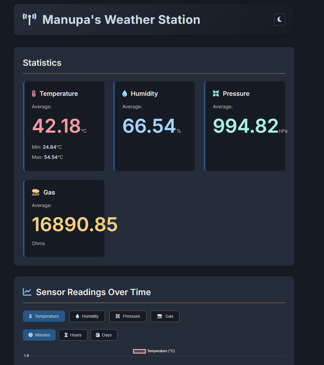
Average Sensor Readings: Displays summarized information for various sensors.
Historical Data Visualization: Allows users to view past data, classified by minutes, hours, and days.
Data Export: The entire database can be downloaded as a CSV file for offline analysis or use by customers.
Navigating Deployment Challenges: From VMs to App Services
I tried deploying the system in a VM in Azure, but I faced several issues:
Lack of HTTPS out-of-the-box: Securing the application required manual SSL certificate configuration.
No Friendly URL: Access was via a public IP address, which isn't user-friendly.
Security Concerns: Managing security on a VM can be complex.
Manual Management: Updates and maintenance were time-consuming.
Performance Issues: Lower-tier (SKU) VMs often froze under load.
After discussing these issues with friends, (Thank you Tharindu 😉) the clear recommendation was to containerize the application using Docker and deploy it as an Azure App Service. This approach offered a much smoother path.
Azure App Services provides various ways to run web applications, including options for static web apps, web apps with databases, and WordPress sites. Given my need for a dynamic application with features like persistent storage and a separate, continuously running data logger, I opted for the Web App service.
To streamline deployment, I packaged the entire project, including the Flask application and the Python data logger, into a Docker image. This image was then pushed to GitLab's Container Registry and made public, allowing Azure App Services to easily pull and deploy it.
You can select your container from different sources when setting up the App Service.
I'm thrilled to say the system is now running smoothly! The final website is accessible, secure, and much easier to manage.
This project was a fantastic learning experience. I now have a secure (HTTPS-enabled) application with minimal maintenance overhead, thanks to Azure App Services. It also benefits from inbuilt scaling capabilities and protection mechanisms like Azure Front Door (if configured).
Future Enhancements 🛠️
While the current version is a significant step up, there are a couple of features I plan to add next:
User Authentication: Implement a sign-in page to manage access for different users.
Integrated Database Solution: Migrate data storage from the SQLite database within the Docker container (which can be difficult to access for direct downloads) to Azure's inbuilt database services. This will make data management and backups more robust and accessible.
Solar Weather Station with Supercapacitors | A Modern Approach
Powering the Future: Integrating a Miniature Weather Station with Solar and Supercapacitors
Published on: May 10, 2025
In our ongoing exploration of innovative solutions for sustainability, I've embarked on a project to integrate a miniature weather station with solar power. To ensure reliability and longevity, we've opted for the use of a supercapacitor as our backup energy storage solution. This post details the journey, the technology, and the performance insights.
Starting the Journey with Supercapacitors
I began by testing the application of supercapacitors in various projects. This experience has been invaluable as I now want to apply what we’ve learned to make our weather station more sustainable and efficient.
Converting Our Miniature Weather Station to Solar-Powered Operation
The next phase of this project involves converting the miniature weather station to run on solar power. By integrating a supercapacitor, which acts as a buffer between the variable output of solar panels and the constant demand from our weather station sensors, we can achieve reliable and consistent readings even during periods of low sunlight.
Why Supercapacitors?
2.7V 30F Supercapacitor
Supercapacitors offer several advantages over traditional batteries such as lithium batteries. Here are the key reasons why they are well-suited for our solar-powered weather station project:
High Power Density
Quick Current Delivery: Deliver high currents quickly, suitable for intermittent and peak loads.
Immediate Response to Demand: Provide immediate power when needed, ensuring consistent readings during low sunlight periods.
Long Cycle Life
Improved Efficiency: Maintain efficiency better under frequent discharges and recharges.
Reliability in Variable Conditions: Robust performance in varying environments (e.g., hot direct sunlight), ensuring consistent operation over time.
Environmental Considerations of Traditional Batteries
While supercapacitors offer benefits, it's also worth noting the environmental impact of traditional battery solutions they can help mitigate:
E-waste Concerns: Traditional batteries can pose significant e-waste issues due to toxic components (like heavy metals) and high recycling costs or complexities.
Resource Intensive: The manufacturing of many battery types requires substantial resources (e.g., lithium, cobalt), the extraction and processing of which can have considerable environmental implications.
Opting for solutions like supercapacitors, especially in applications where their characteristics are a good fit, can contribute to reducing these environmental burdens.
The Solution: A Block-by-Block Breakdown
My project breaks down into several key stages, utilizing the following main components:
ESP32C3 Supermini: The microcontroller brain.
BME680 Module: The environmental sensor.
TPS63802 Buck Boost Converter Module: For stable power delivery.
Solar Panel (5V 200mA): For energy harvesting.
Supercapacitors (2x 2.7V 30F in series): For energy storage.
The process involves:
Energy Harvesting: Capturing sunlight using a solar panel.
Energy Storage: Storing the harvested energy using supercapacitors.
Power Management: Providing a stable voltage to the microcontroller and sensor despite fluctuating storage voltage.
The Brain: An ESP32C3 microcontroller handling sensor reading, WiFi, and data transmission.
The Sensor: A BME680 measuring temperature, humidity, pressure, and gas resistance.
The Software: Firmware running on the ESP32C3 to control everything.
Let's look at each part in more detail.
1. Harvesting Sunlight: The Solar Panel
The energy source for this project is a 5V 200mA solar panel. This is a standard, relatively small panel suitable for low-power applications. It captures sunlight and converts it into electrical energy.
2. Storing the Energy: Supercapacitors
Instead of a traditional battery, I'm using two 2.7V 30F supercapacitors connected in series. Supercapacitors are fantastic for this kind of application because they can charge and discharge very quickly and tolerate a huge number of cycles compared to batteries.
Series Connection: Connecting the two 2.7V caps in series allows them to handle a higher total voltage (up to 5.4V). However, connecting capacitors in series reduces the total capacitance – in this case, two 30F caps in series behave like a single 15F capacitor.
Charging Protection: A diode is connected in series between the solar panel and the supercapacitors. This is crucial! It acts as a one-way valve, allowing current to flow from the solar panel to the supercapacitors, but preventing the stored energy in the supercapacitors from flowing back into the solar panel when the sun isn't providing enough voltage (like at night).
Balancing Act: When connecting capacitors (especially supercapacitors) in series, it's essential to ensure the voltage is shared equally across them. I've implemented voltage balancing using 4.8 MegaOhm resistors connected in parallel with each supercapacitor. These resistors help bleed off excess voltage, allowing the voltage to equalize. For more on this, see resources like the Analog Devices document on supercapacitor balancing.
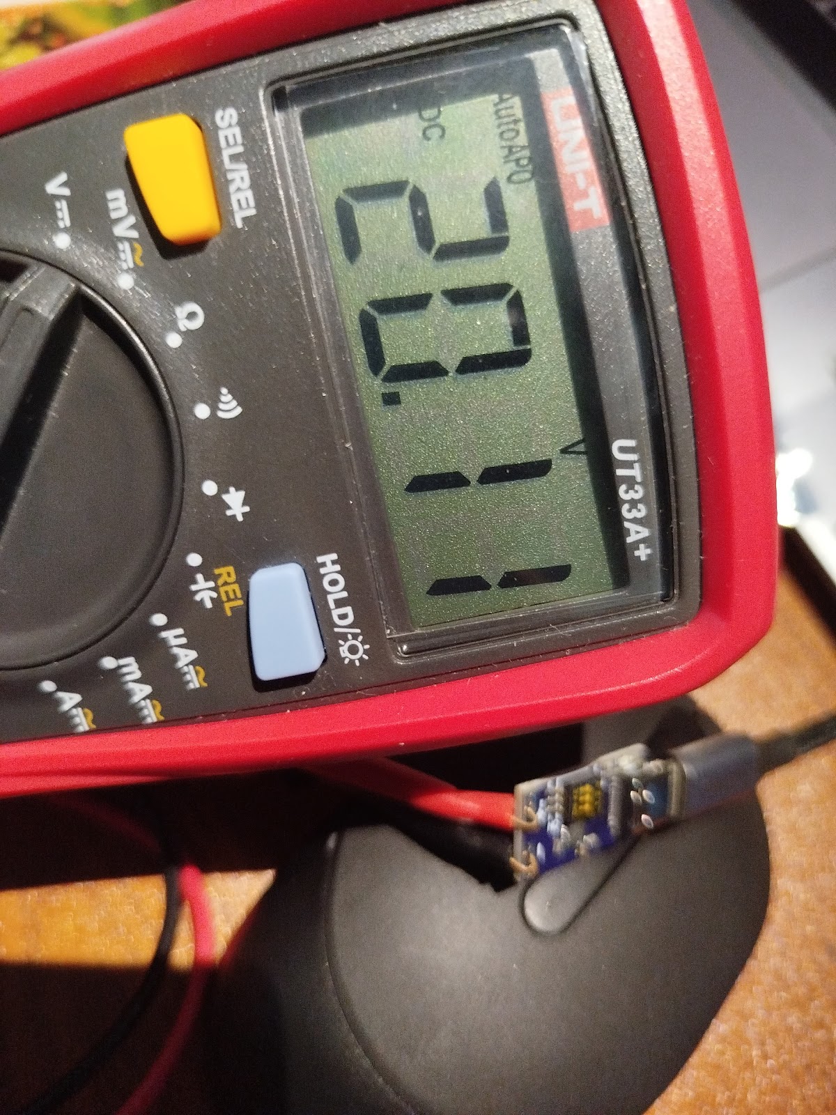
3. Stable Power for the Electronics: The Buck-Boost Module
The voltage stored in the supercapacitors will fluctuate (from near 0V up to ~5.4V). Microcontrollers and sensors need a stable operating voltage. This is where the TPS63802 Buck-Boost module comes in. It takes the fluctuating voltage from the supercapacitors and converts it into a stable 3.3V output, ideal for the ESP32C3 and BME680. (The module can also be set to 4.2V or 5V).
TPS63802 Buck-Boost Converter Module.
4. The Brains: ESP32C3 Microcontroller
The core of the system is the ESP32C3, a modern, low-power microcontroller with built-in WiFi. It's responsible for:
ESP32C3 Supermini.
Initializing and reading data from the BME680 sensor.
Managing WiFi connectivity.
Formatting the sensor data.
Publishing the data to an MQTT broker.
Potentially managing power modes (area for future optimization).
5. The Sensor: Bosch BME680
For environmental data, I chose the BME680 sensor. This single module from Bosch measures:
BME680 Environmental Sensor.
Temperature
Relative Humidity
Barometric Pressure
Gas Resistance (related to air quality)
The Software: Firmware and Libraries
Bringing the hardware to life requires robust software. The firmware running on the ESP32C3 is based on an open-source project specifically designed for interfacing with the BME680 and connecting via WiFi/MQTT. The code I'm using is from this repository: manupawickramasinghe/bme680-wifi-sensor-firmware.
This firmware is built using the ESP-IDF framework (Espressif IoT Development Framework) and leverages an open-source driver for the BME680: gschorcht/bme680-esp-idf.
Here's a summary of the key features provided by this firmware:
Multi-Interface Support: Communicates with BME680 via I2C or SPI.
ESP32/ESP8266 Support: Compatible with various ESP platforms.
WiFi Connectivity: Includes SmartConfig for easy provisioning.
MQTT Data Publishing: Sends sensor readings to an MQTT broker.
Automated Builds and Testing: CI/CD using GitHub Actions for code quality.
Structured Data Output: Formats sensor readings into JSON for MQTT.
This firmware provides a solid foundation, handling the complexities of the BME680 interface, WiFi connectivity, and data transmission.
How It All Comes Together
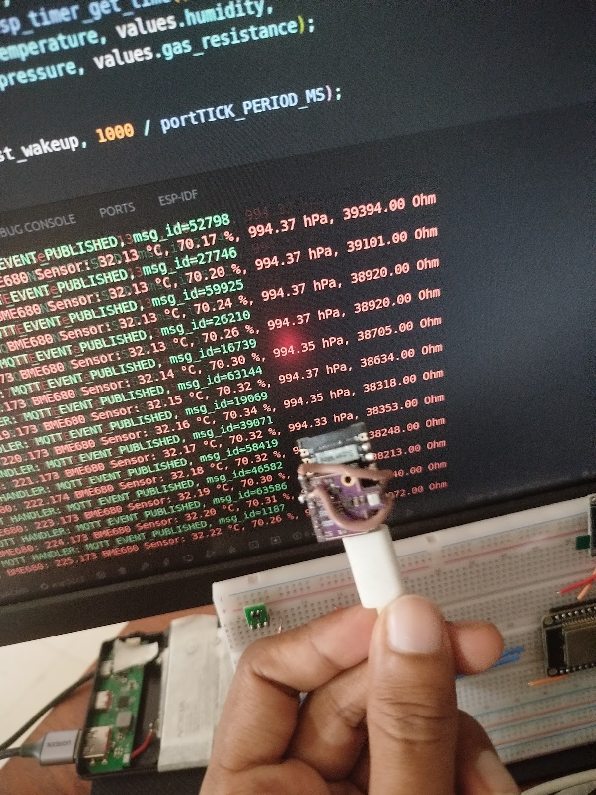
In summary, sunlight hits the solar panel, its energy is directed via the diode into the supercapacitors for storage (kept balanced by resistors). The TPS63802 buck-boost takes the variable voltage from the supercaps and outputs a stable 3.3V. This 3.3V powers the ESP32C3 and the BME680 sensor. The ESP32C3, running the custom firmware, reads data from the BME680, connects to the local WiFi network, and publishes the environmental readings as a JSON message to an MQTT broker.
The assembled electronics package, ready for deployment.
This creates a self-sufficient system capable of monitoring temperature, humidity, pressure, and air quality, powered entirely by the sun and stored energy in the supercapacitors.
Performance Insights: What the Data Tells Us
Analyzing the collected data revealed a lot about the system's behavior:
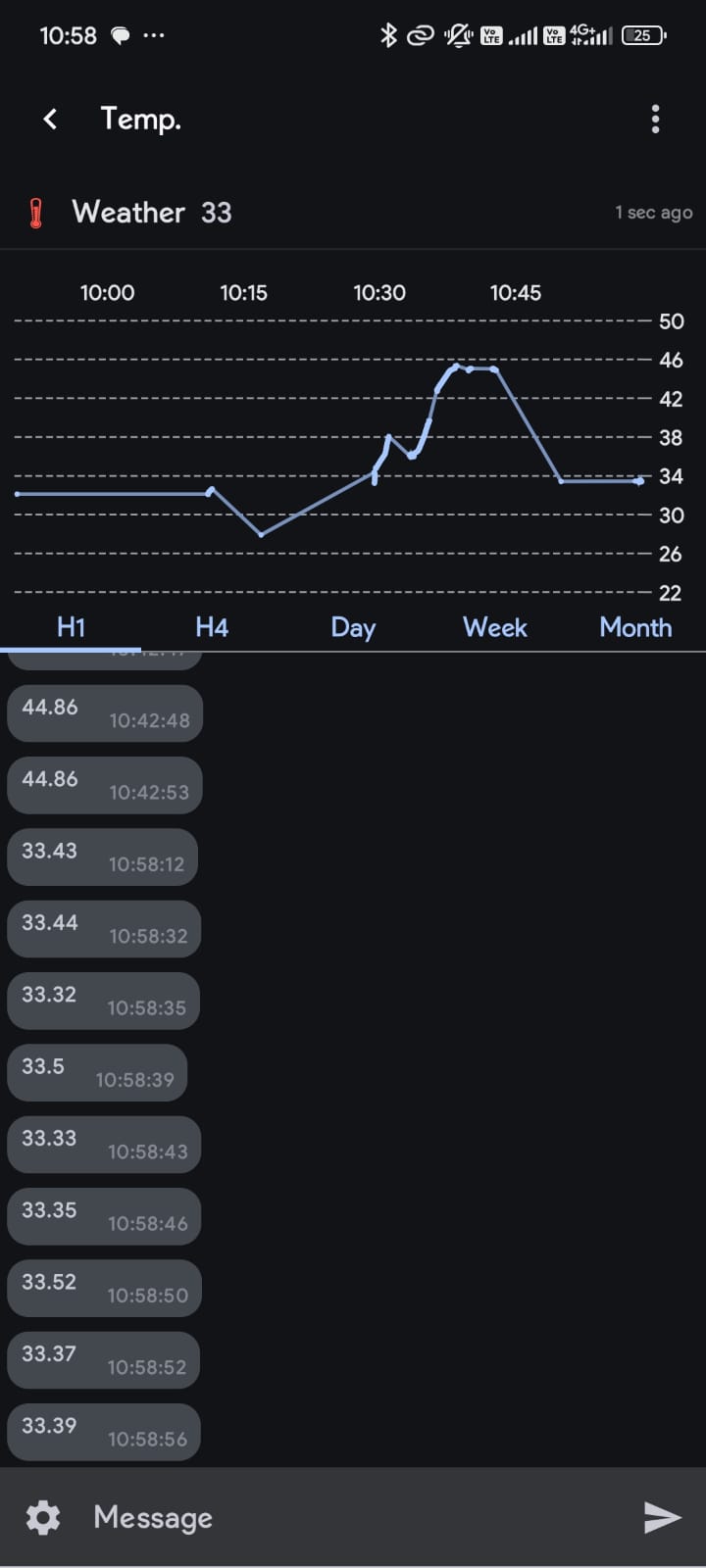
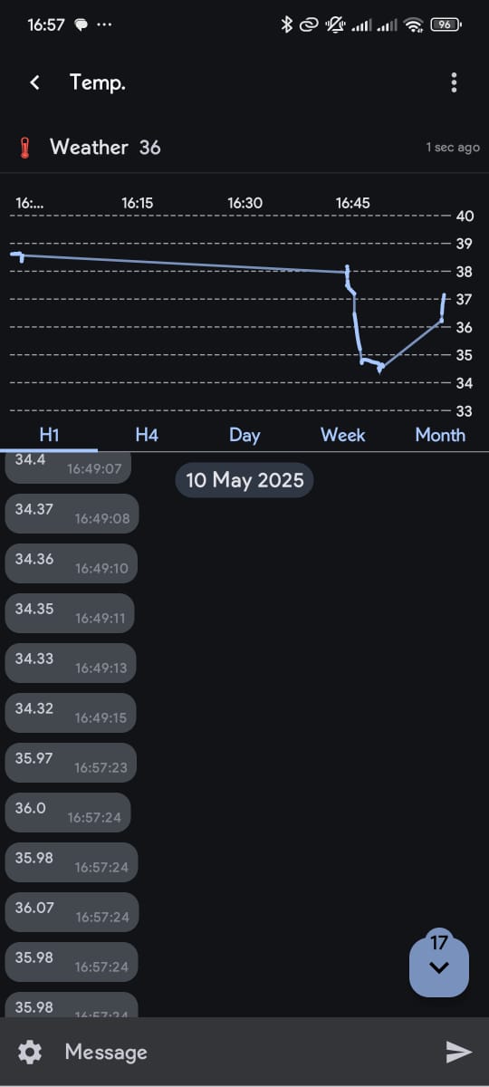
Temperature Trends: We see the expected daily warming/cooling and the sensor's fine resolution (small ±0.02 °C noise).
Location Impact: A significant peak spike up to ~46°C highlighted a major issue: the sensor wasn't measuring ambient air, but the heat from hot concrete it was initially placed on. Relocating helped mitigate this.
Power Fluctuation Noise: Subtle temperature jitter was more apparent in the morning and evening, likely linked to power instability during low light/charging transitions.
Crucially, the data reporting frequency varied significantly based on light conditions:
Morning (7 AM+): Starts slow (~15 min/message), increasing to ~5 min/message as sunlight intensifies.
Mid-day (10 AM+): Becomes very frequent (almost every second) under full sun. Clouds cause it to drop back to 5-15 mins.
Evening (After 5 PM): Frequency drops drastically (5-15 mins -> 30 mins), stopping completely after 6:30/7 PM as supercapacitors deplete without solar input.
This changing frequency is a direct indicator of the system reacting to available solar power and supercapacitor voltage. More light means more power, allowing the ESP32 to operate and transmit more often. Less light means less power, forcing it to slow down or eventually enter deep sleep until sufficient charge is regained.
Current Limitations & What's Next
While the project is operational and demonstrates the concept effectively, I've identified a few areas for improvement and future development:
Sensor Accuracy: The BME680 is sensitive to heat generated by the ESP32C3 itself, which can affect temperature and humidity readings if not properly isolated.
Future: Design an enclosure that physically separates the sensor from the main microcontroller board, ensuring better airflow around the sensor.
Placement Heat: Initial tests showed that heat absorbed and radiated from the surface the device sits on (e.g., concrete) can significantly skew readings.
Solution: The device is now mounted on a wooden pole to minimize ground heat interference and improve air circulation.
Power Efficiency: The current firmware isn't fully optimized for ultra-low power consumption, potentially draining the supercapacitors faster than ideal during prolonged low-light conditions.
Future: Implement aggressive ESP32C3 Deep Sleep modes, optimize WiFi connection/disconnection times, minimize active mode duration, and refine supercapacitor balancing for minimal quiescent current.
Solar Charging Circuit: The current simple diode-based charging is functional but incurs a voltage drop.
Future: Explore more efficient solar charging ICs (e.g., MPPT controllers suitable for low power) to maximize energy harvesting and reduce losses.
Breathing New Life: Building a Home Server from Old Laptops
Breathing New Life: My DIY Home Server Project! 💻➡️🏠
Turning e-waste into a useful home lab with a bit of tinkering.
The Spark ✨: Old Laptops Get a Second Chance
Recently, a friend gifted me some old laptops. Instead of letting them gather dust or become e-waste, I saw an opportunity! 💡 Why not build a home server? It's a great way to learn, host services, and make use of hardware that might otherwise be discarded.
The challenge? These laptops came barebones – no SSD, no RAM, and crucially, no power adapter! But where there's a will (and some spare parts), there's a way.
The Hardware Hustle 🛠️: Powering Up!
The biggest hurdle was power. Luckily, I had a nifty USB-C PD Fast Charger Decoy Board (100W capable!) lying around. These little boards can negotiate specific voltages from USB-C Power Delivery chargers.
The laptop needed 19V via its barrel jack. I configured the decoy board's DIP switches to request 20V from my USB-C charger (close enough!). Then came the slightly nerve-wracking part: soldering! 👨🏭
Identified the positive (+) and ground (-) pins on the laptop's power input.
Soldered the decoy board's output wires directly to these points.
Carefully cut a small slot in the laptop's casing to neatly house the board.
Used strong double-sided tape to secure the board inside.
Plugged in the USB-C charger, held my breath... and success! 🎉 The laptop powered on, drawing juice through the new setup. Phew!
Next, I installed some spare DDR3 RAM and an old SATA SSD I had available. Hardware complete! ✅
The Software Stack 🐧🐳: Ubuntu & Docker
With the hardware sorted, it was time for the operating system. I opted for Ubuntu Server – it's stable, widely supported, and great for server tasks. Installation was straightforward via a USB drive.
To manage the various services I wanted to run, I decided to use Docker. Containers make it super easy to install, run, and manage applications in isolated environments. No more dependency nightmares! 🐳
Installing Docker on Ubuntu:
# Update package list
sudo apt update

# Install prerequisites
sudo apt install -y apt-transport-https ca-certificates curl software-properties-common

# Add Docker's official GPG key
curl -fsSL https://download.docker.com/linux/ubuntu/gpg | sudo gpg --dearmor -o /usr/share/keyrings/docker-archive-keyring.gpg

# Add Docker repository
echo "deb [arch=$(dpkg --print-architecture) signed-by=/usr/share/keyrings/docker-archive-keyring.gpg] https://download.docker.com/linux/ubuntu $(lsb_release -cs) stable" | sudo tee /etc/apt/sources.list.d/docker.list > /dev/null

# Install Docker Engine
sudo apt update
sudo apt install -y docker-ce docker-ce-cli containerd.io

# Add your user to the docker group (to run docker without sudo - log out/in after)
sudo usermod -aG docker ${USER}

# Verify installation
docker --version
Note: You'll need to log out and log back in for the group change (`usermod`) to take effect.
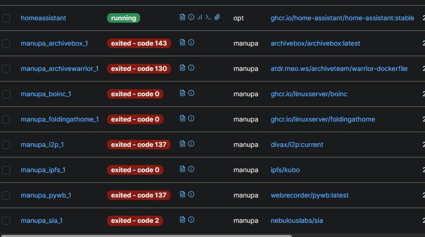
My Container Crew 🚀: Services Running
Here are the initial containers I set up:
🗄️ ArchiveBox (Good Karma Kit)
This awesome tool creates local, browsable archives of websites. Perfect for saving articles, documentation, or anything important online before it disappears. The Good Karma Kit aspect seems focused on archiving public interest content.
Access it at `http://[your-server-ip]:8000`. Replace `~/archivebox_data` with your desired host path for data storage.
🚢 Portainer
Managing Docker containers via the command line is fine, but Portainer provides a fantastic web UI. It makes it easy to view logs, manage containers, networks, volumes, and more. Highly recommended for managing your Docker environment!
Docker Run Command (Portainer CE):
# First, create a volume for Portainer data
docker volume create portainer_data

# Then, run the Portainer container
docker run -d \
  -p 8000:8000 \
  -p 9443:9443 \
  --name portainer \
  --restart=always \
  -v /var/run/docker.sock:/var/run/docker.sock \
  -v portainer_data:/data \
  portainer/portainer-ce:latest
Access it at `https://[your-server-ip]:9443` (HTTPS) or `http://[your-server-ip]:8000`. You'll set up an admin user on first access.
🎬 Plex Media Server
No home server is complete without a media solution! Plex organizes your movies, TV shows, music, and photos, allowing you to stream them to virtually any device, anywhere. It scans your media folders and automatically fetches metadata and artwork.
Access the setup wizard at `http://[your-server-ip]:32400/web`. Make sure the paths you map (`/path/to/...`) exist on your host system and have correct permissions.
🏠 Home Assistant
Home Assistant! It's an incredibly powerful open-source home automation platform. You can integrate smart devices, create automations, track sensors, and build amazing dashboards.
Access it at `http://[your-server-ip]:8123`. Replace `/path/to/homeassistant/config` with your desired config path. `--network=host` is often needed for device discovery.
📊 btop++ (Resource Monitor)
While not typically run as a Docker container, `btop++` is an excellent TUI (Text User Interface) resource monitor. It gives a detailed, real-time view of CPU, memory, disk, and network usage right in your terminal. Very handy for seeing how the server is performing!
Installation Command (Ubuntu):
sudo apt update
sudo apt install -y btop
Usage:
btop
Smart Scheduling ⏰: Working Around Data Caps
My ISP offers unlimited data during off-peak hours (midnight to 7 AM). To take advantage of this for potentially data-intensive tasks (like ArchiveBox fetching sites), I set up a cron job. Cron is a time-based job scheduler in Unix-like operating systems.
I scheduled tasks to automatically stop certain containers at 7 AM and start them again at midnight. This helps manage bandwidth usage and costs effectively. 💰
Example Cron Job (Edit with `crontab -e`):
# Stop ArchiveBox container at 7:00 AM daily
0 7 * * * docker stop archivebox

# Start ArchiveBox container at 00:00 AM (midnight) daily
0 0 * * * docker start archivebox
You'd add similar lines for any other containers you want to schedule.
What's Next? 🤔 More Containers!
This is just the beginning! I'm excited to explore more self-hosted applications. What other containers do you recommend for a home server setup?
Some popular ideas include:
Nextcloud ☁️: Your own private cloud for files, calendars, contacts, and more (like Google Drive/Dropbox).
Pi-hole 🚫: Network-wide ad blocker. Say goodbye to most ads on all your devices!
Dumping STM32F105 Firmware on Ubuntu using ST-LINKMB_CAN_Filter Board
I recently got a CAN bus filter from AliExpress MB_CAN_FIlter. The existing firmware is used to bypass the Odometer of the premium cars like Mercedes, BMW by modifying the CAN signal that are passed through it. But we can utilize this for better endeavors like resetting the BMS signals of EVs to expand the lifetime of the battery and replacing batteries of higher capacity.
So it is essential to understand how this Circuit works, and learn the Basics of dumping the existing firmware and flashing new firmware to the Chip it is using.
The board here uses a STM32F105C8T6 Microcontroller and the CAN Transceivers ICs are some TJA1057. There is a similar board that uses the MCP2551.
There are multiple reasons why this board is wonderful as well as has many issues related to the PCB in which I will be going through maybe will opensource the designs in the future.
Dumping STM32F105 Firmware on Ubuntu using ST-LINK
This guide details how to install the required tools and dump the firmware from an STM32F105 microcontroller using an ST-LINK programmer on an Ubuntu system. We will cover two common tools: STM32CubeProgrammer (the official ST tool) and OpenOCD (an open-source alternative).
1. Prerequisites
Hardware:
STM32F105-based board (See Section 3 for a specific example).
ST-LINK V2 or V3 programmer/debugger.
USB cables for the ST-LINK and potentially the target board (if it needs separate power).
Jumper wires for SWD connection.
Software:
Ubuntu Linux (instructions tested on recent LTS versions like 20.04/22.04).
Internet connection for downloads.
2. Tool Installation
a) STM32CubeProgrammer
STM32CubeProgrammer is STMicroelectronics' official tool for programming STM32 devices. It replaces older tools like ST-LINK Utility and STM Flasher.
Install Java: CubeProgrammer requires Java. Check if it's installed and install it if necessary:
java -version
# If not installed or version is too old:
sudo apt update
sudo apt install default-jre -y
Extract: Unzip the downloaded file:
unzip en.stm32cubeprg-lin_*.zip -d stm32cubeprogrammer
cd stm32cubeprogrammer
Run Installer: Execute the Linux installer script. You might need to make it executable first.
chmod +x SetupSTM32CubeProgrammer*.linux
sudo ./SetupSTM32CubeProgrammer*.linux
# Or run without sudo for user-local installation if preferred
# ./SetupSTM32CubeProgrammer*.linux
Follow the on-screen installation steps. The default installation location is often /usr/local/STMicroelectronics/STM32Cube/STM32CubeProgrammer/.
Add to PATH (Optional): To run the command-line interface (CLI) easily, add its directory to your PATH. Find the bin directory within your installation path (e.g., /usr/local/STMicroelectronics/STM32Cube/STM32CubeProgrammer/bin) and add it to your ~/.bashrc or ~/.zshrc:
sudo udevadm control --reload-rules
sudo udevadm trigger
Reconnect: Unplug and replug your ST-LINK programmer.
3. Hardware Overview (User's Board Example)
This section describes the specific hardware components mentioned for the target board being used in this example.
Microcontroller:STM32F105C8T6
Rationale: This MCU from the STM32F1 series (Connectivity Line) is chosen primarily for its dual CAN interfaces (bxCAN), which is essential for applications requiring communication on two separate CAN buses (e.g., bridging, gateway). Additionally, many of its GPIO pins are 5V tolerant, which simplifies interfacing with 5V peripherals like some CAN transceivers, although direct connection still requires careful consideration of signal levels.
CAN Transceiver:TJA1057
Rationale: This is a high-speed CAN transceiver. Compared to other common options in the TJA10xx family (like the TJA1050), the TJA1057 often provides improved ElectroMagnetic Compatibility (EMC) and ElectroStatic Discharge (ESD) performance. It might also offer features like specific low-power modes or better behavior under bus fault conditions, making it a robust choice for CAN communication.
Voltage Regulators:AMS1117-3.3 (3.3V LDO) and AMS1117-5.0 (5V LDO)
Function: These are Linear Low-Dropout regulators used to provide stable 3.3V (for the MCU and potentially other logic) and 5V (likely for the CAN transceiver VCC or other peripherals) from a higher input voltage.
Potential Board Design Considerations/Issues:
LDO Inefficiency: Using AMS1117 LDOs, especially for significant voltage drops (e.g., 12V input down to 5V or 3.3V) or higher current demands, leads to power loss as heat. This can reduce overall efficiency and potentially require heatsinking. Switch-mode buck converters are generally more efficient but add complexity and potential noise. LDOs like the AMS1117 also require specific types and values of input/output capacitors for stability, which must be correctly implemented.
Non-Automotive Grade MCU: The STM32F105C8T6 is typically a commercial or industrial grade component. If the application is intended for automotive environments, using a non-automotive qualified MCU might pose risks regarding temperature range limitations, long-term reliability, and lack of specific automotive certifications (AEC-Q100).
Lack of Feedback LEDs: The absence of status LEDs (e.g., Power OK, CAN TX/RX activity, Heartbeat) makes visual debugging and diagnostics difficult. It's hard to tell if the board is powered correctly or if communication is active without external measurement tools.
Noise Reduction and EMI Protection: For reliable CAN communication, especially at high speeds or in noisy environments, careful PCB layout, proper CAN bus termination (e.g., 120-ohm resistors), common-mode chokes, and potentially transient voltage suppression (TVS) diodes are crucial. Lacking these can lead to communication errors or susceptibility to electromagnetic interference.
4. Connecting Hardware (ST-LINK SWD)
Connect the ST-LINK programmer to your STM32F105 board using the SWD interface:
ST-LINK SWDIO <--> Target SWDIO (often PA13)
ST-LINK SWCLK <--> Target SWCLK (often PA14)
ST-LINK GND <--> Target GND
ST-LINK VCC/VDD <--> Target VDD (usually 3.3V, ensure voltage matches the MCU's VDD)
(Optional but Recommended) ST-LINK NRST <--> Target NRST (Reset pin)
Ensure the target board is powered on (using its own power supply, likely regulated by the onboard AMS1117s).
5. Dumping Firmware
The STM32F105 typically has Flash memory starting at address 0x08000000. The size varies; the C8 variant usually has 64KB (0x10000 bytes), but the F105 line goes up to 256KB (0x40000 bytes). Verify the exact flash size for your STM32F105C8T6 (it's 64KB) and adjust the size parameter accordingly.
This command attempts to connect via SWD at 4MHz and read a device ID register. It should output some information about the connected device if successful.
Read Flash to Binary File (for STM32F105C8T6 - 64KB):
# Use 0x10000 for 64KB Flash size
STM32_Programmer_CLI -c port=SWD freq=4000 mode=NORMAL -r 0x08000000 0x10000 firmware_dump.bin
This reads 64KB (0x10000 bytes) starting from address 0x08000000 and saves it to firmware_dump.bin.
Read Flash to Hex File (for STM32F105C8T6 - 64KB):
This saves the firmware in Intel HEX format instead of raw binary.
b) Using OpenOCD
Start OpenOCD: Open a terminal and run:
# Use stlink-v2.cfg for ST-LINK V2, stlink.cfg often works for V2/V3
# stm32f1x.cfg is the target configuration for the STM32F1 series
openocd -f interface/stlink.cfg -f target/stm32f1x.cfg
OpenOCD connection output example
OpenOCD will try to connect to the target. Look for output indicating successful connection and halting the target CPU. It should also detect the flash size (likely reporting 64k).
Connect via Telnet: Open another terminal window and connect to the OpenOCD server (which listens on port 4444 by default):
telnet localhost 4444
Telnet connection output
Halt CPU (if not already halted):
> halt
Dump Firmware (for STM32F105C8T6 - 64KB): Use the dump_image command:
# dump_image <filename> <address> <size>
# Use 0x10000 for 64KB flash size
> dump_image firmware_dump_openocd.bin 0x08000000 0x10000
This command reads 64KB from flash address 0x08000000 and saves it to firmware_dump_openocd.bin in the directory where you launched OpenOCD.
Exit Telnet: Type exit and press Enter.
Shutdown OpenOCD: Go back to the first terminal (where OpenOCD is running) and press Ctrl+C to stop it.
6. Troubleshooting
Permission Denied / Cannot Open Device: Ensure udev rules are correctly set up and applied, or run the command using sudo (not recommended for regular use).
Cannot Connect / Target Not Found:
Double-check SWD wiring (SWDIO, SWCLK, GND, VDD).
Ensure the target board is powered correctly via its regulators.
Try lowering the SWD frequency (freq=1000 in CubeProgrammer, adapter speed 1000 in OpenOCD telnet session).
Try connecting under reset: Use mode=UR (Under Reset) in CubeProgrammer, or add connect_assert_srst to the OpenOCD command line before -f target/.... Ensure the NRST line is connected.
Check if the debug pins (SWDIO/SWCLK) have been disabled by the firmware. If so, connecting under reset might be the only option.
OpenOCD Errors: Pay attention to the specific error messages. Sometimes the wrong interface or target script is used. Ensure the detected flash size matches your expectation (64k for C8T6).
You now have the firmware dumped as a .bin or .hex file, which you can analyze or use as a backup.
From each step it is possible to Dump the Firmware.
Using OpenOCD we can also reset the fuses that are used in the MCU, if you look at the code, I reset the fuses that had set the STM32 to read only mode. Doing so can reduce the effects of corruption of the firmware.