

Powering the Future: Integrating a Miniature Weather Station with Solar and Supercapacitors
Published on: May 10, 2025
In our ongoing exploration of innovative solutions for sustainability, I've embarked on a project to integrate a miniature weather station with solar power. To ensure reliability and longevity, we've opted for the use of a supercapacitor as our backup energy storage solution. This post details the journey, the technology, and the performance insights.
Starting the Journey with Supercapacitors
I began by testing the application of supercapacitors in various projects. This experience has been invaluable as I now want to apply what we’ve learned to make our weather station more sustainable and efficient.
Converting Our Miniature Weather Station to Solar-Powered Operation
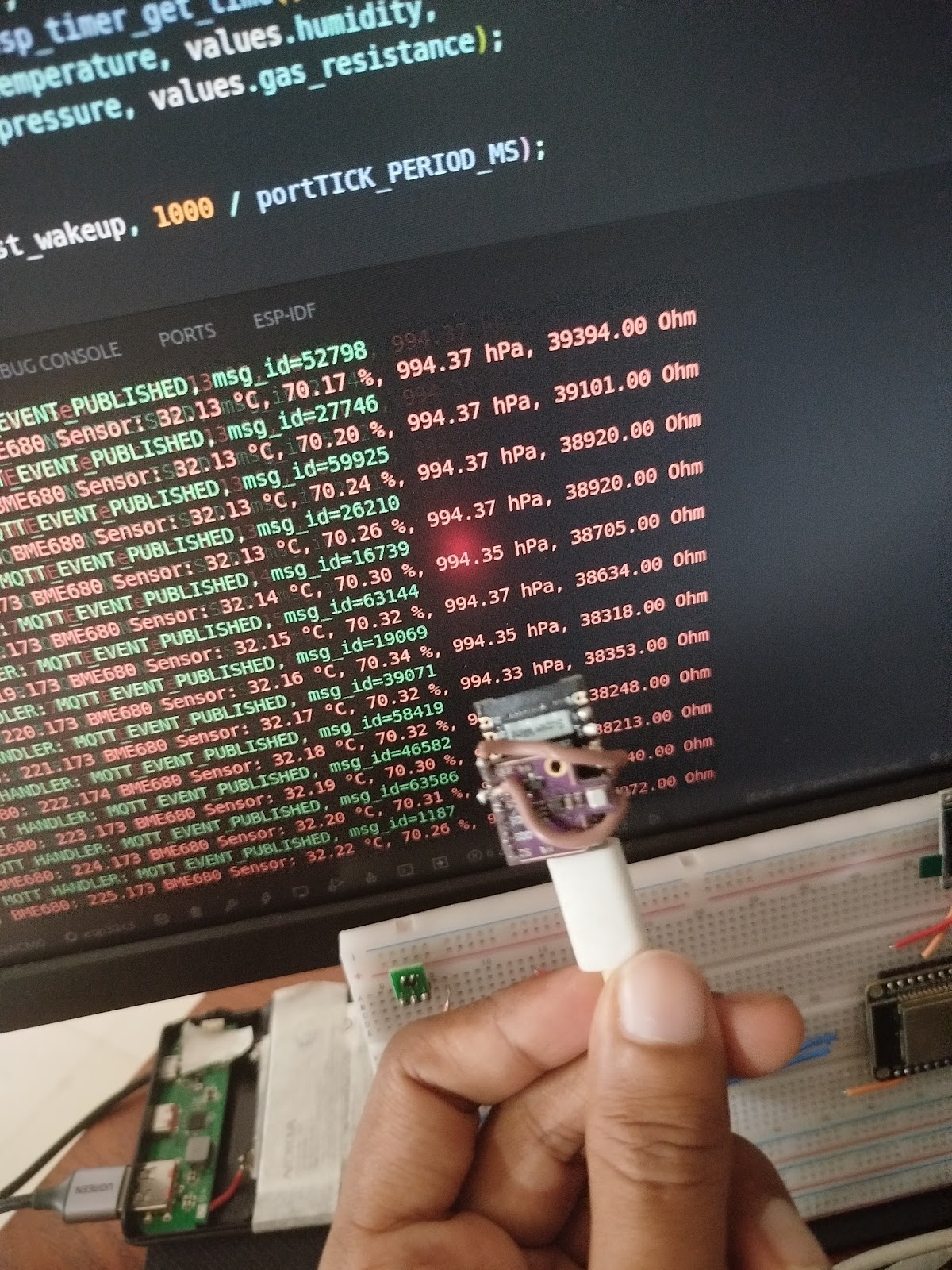
The next phase of this project involves converting the miniature weather station to run on solar power. By integrating a supercapacitor, which acts as a buffer between the variable output of solar panels and the constant demand from our weather station sensors, we can achieve reliable and consistent readings even during periods of low sunlight.
Why Supercapacitors?

2.7V 30F Supercapacitor
Supercapacitors offer several advantages over traditional batteries such as lithium batteries. Here are the key reasons why they are well-suited for our solar-powered weather station project:
High Power Density
- Quick Current Delivery: Deliver high currents quickly, suitable for intermittent and peak loads.
- Immediate Response to Demand: Provide immediate power when needed, ensuring consistent readings during low sunlight periods.
Long Cycle Life
- Improved Efficiency: Maintain efficiency better under frequent discharges and recharges.
- Reliability in Variable Conditions: Robust performance in varying environments (e.g., hot direct sunlight), ensuring consistent operation over time.
Environmental Considerations of Traditional Batteries
While supercapacitors offer benefits, it's also worth noting the environmental impact of traditional battery solutions they can help mitigate:
- E-waste Concerns: Traditional batteries can pose significant e-waste issues due to toxic components (like heavy metals) and high recycling costs or complexities.
- Resource Intensive: The manufacturing of many battery types requires substantial resources (e.g., lithium, cobalt), the extraction and processing of which can have considerable environmental implications.
Opting for solutions like supercapacitors, especially in applications where their characteristics are a good fit, can contribute to reducing these environmental burdens.
The Solution: A Block-by-Block Breakdown
My project breaks down into several key stages, utilizing the following main components:
- ESP32C3 Supermini: The microcontroller brain.
- BME680 Module: The environmental sensor.
- TPS63802 Buck Boost Converter Module: For stable power delivery.
- Solar Panel (5V 200mA): For energy harvesting.
- Supercapacitors (2x 2.7V 30F in series): For energy storage.
The process involves:
- Energy Harvesting: Capturing sunlight using a solar panel.
- Energy Storage: Storing the harvested energy using supercapacitors.
- Power Management: Providing a stable voltage to the microcontroller and sensor despite fluctuating storage voltage.
- The Brain: An ESP32C3 microcontroller handling sensor reading, WiFi, and data transmission.
- The Sensor: A BME680 measuring temperature, humidity, pressure, and gas resistance.
- The Software: Firmware running on the ESP32C3 to control everything.
Let's look at each part in more detail.
1. Harvesting Sunlight: The Solar Panel
The energy source for this project is a 5V 200mA solar panel. This is a standard, relatively small panel suitable for low-power applications. It captures sunlight and converts it into electrical energy.
2. Storing the Energy: Supercapacitors
Instead of a traditional battery, I'm using two 2.7V 30F supercapacitors connected in series. Supercapacitors are fantastic for this kind of application because they can charge and discharge very quickly and tolerate a huge number of cycles compared to batteries.
- Series Connection: Connecting the two 2.7V caps in series allows them to handle a higher total voltage (up to 5.4V). However, connecting capacitors in series reduces the total capacitance – in this case, two 30F caps in series behave like a single 15F capacitor.
- Charging Protection: A diode is connected in series between the solar panel and the supercapacitors. This is crucial! It acts as a one-way valve, allowing current to flow from the solar panel to the supercapacitors, but preventing the stored energy in the supercapacitors from flowing back into the solar panel when the sun isn't providing enough voltage (like at night).
- Balancing Act: When connecting capacitors (especially supercapacitors) in series, it's essential to ensure the voltage is shared equally across them. I've implemented voltage balancing using 4.8 MegaOhm resistors connected in parallel with each supercapacitor. These resistors help bleed off excess voltage, allowing the voltage to equalize. For more on this, see resources like the Analog Devices document on supercapacitor balancing.
3. Stable Power for the Electronics: The Buck-Boost Module
The voltage stored in the supercapacitors will fluctuate (from near 0V up to ~5.4V). Microcontrollers and sensors need a stable operating voltage. This is where the TPS63802 Buck-Boost module comes in. It takes the fluctuating voltage from the supercapacitors and converts it into a stable 3.3V output, ideal for the ESP32C3 and BME680. (The module can also be set to 4.2V or 5V).

4. The Brains: ESP32C3 Microcontroller
The core of the system is the ESP32C3, a modern, low-power microcontroller with built-in WiFi. It's responsible for:

- Initializing and reading data from the BME680 sensor.
- Managing WiFi connectivity.
- Formatting the sensor data.
- Publishing the data to an MQTT broker.
- Potentially managing power modes (area for future optimization).
5. The Sensor: Bosch BME680
For environmental data, I chose the BME680 sensor. This single module from Bosch measures:

- Temperature
- Relative Humidity
- Barometric Pressure
- Gas Resistance (related to air quality)
The Software: Firmware and Libraries
Bringing the hardware to life requires robust software. The firmware running on the ESP32C3 is based on an open-source project specifically designed for interfacing with the BME680 and connecting via WiFi/MQTT. The code I'm using is from this repository: manupawickramasinghe/bme680-wifi-sensor-firmware.
This firmware is built using the ESP-IDF framework (Espressif IoT Development Framework) and leverages an open-source driver for the BME680: gschorcht/bme680-esp-idf.
Here's a summary of the key features provided by this firmware:
- Multi-Interface Support: Communicates with BME680 via I2C or SPI.
- ESP32/ESP8266 Support: Compatible with various ESP platforms.
- WiFi Connectivity: Includes SmartConfig for easy provisioning.
- MQTT Data Publishing: Sends sensor readings to an MQTT broker.
- Advanced Sensor Configurations: Allows customization of BME680 settings (oversampling, IIR filter, heater profiles).
- Automated Builds and Testing: CI/CD using GitHub Actions for code quality.
- Structured Data Output: Formats sensor readings into JSON for MQTT.
This firmware provides a solid foundation, handling the complexities of the BME680 interface, WiFi connectivity, and data transmission.
How It All Comes Together
In summary, sunlight hits the solar panel, its energy is directed via the diode into the supercapacitors for storage (kept balanced by resistors). The TPS63802 buck-boost takes the variable voltage from the supercaps and outputs a stable 3.3V. This 3.3V powers the ESP32C3 and the BME680 sensor. The ESP32C3, running the custom firmware, reads data from the BME680, connects to the local WiFi network, and publishes the environmental readings as a JSON message to an MQTT broker.
Conceptual Circuit Diagram:
     +---------------------+     +---------------------+
     | Solar Panel (+)     |     | Solar Panel (-)     |
     +--------|------------+     +------------|--------+
              |                               |
              |  Diode (e.g. Schottky)        |
              |   --->|---                     |
              |    |                          |
              +----o--------------------------+
                   |
                   | Supercapacitor Bank (e.g., 2 in series)
                   |
         +---------+---------+
         |                   |
       -----               -----
R_balance1 || --- C1 (2.7V, 30F)--- || R_balance2
       -----               -----
         |                   |
         +--------o VIN -----+ (Input to Buck-Boost)
                  |
          +-------V-------+
          |  TPS63802     |
          |  Buck-Boost   |------> VOUT (3.3V) ----> VCC_ESP32 & VCC_BME680
          |  Module       |
          +-------|-------+
                  | GND
                  |
------------------o---------------------------------- GND
|                                                    |
|                                                    |
+---------|----------+                             +---------|----------+
|  ESP32-C3          |                             |  BME680 Sensor     |
|                    |                             |                    |
|         GPIO (SDA) o-----------------------------o SDA                |
|         GPIO (SCL) o-----------------------------o SCL                |
|                    |                             |                    |
|              GND   o-----------------------------o GND                |
|              3.3V  o-----------------------------o VCC (from 3.3V VOUT) |
+--------------------+                             +--------------------+

This creates a self-sufficient system capable of monitoring temperature, humidity, pressure, and air quality, powered entirely by the sun and stored energy in the supercapacitors.
Performance Insights: What the Data Tells Us
Analyzing the collected data revealed a lot about the system's behavior:
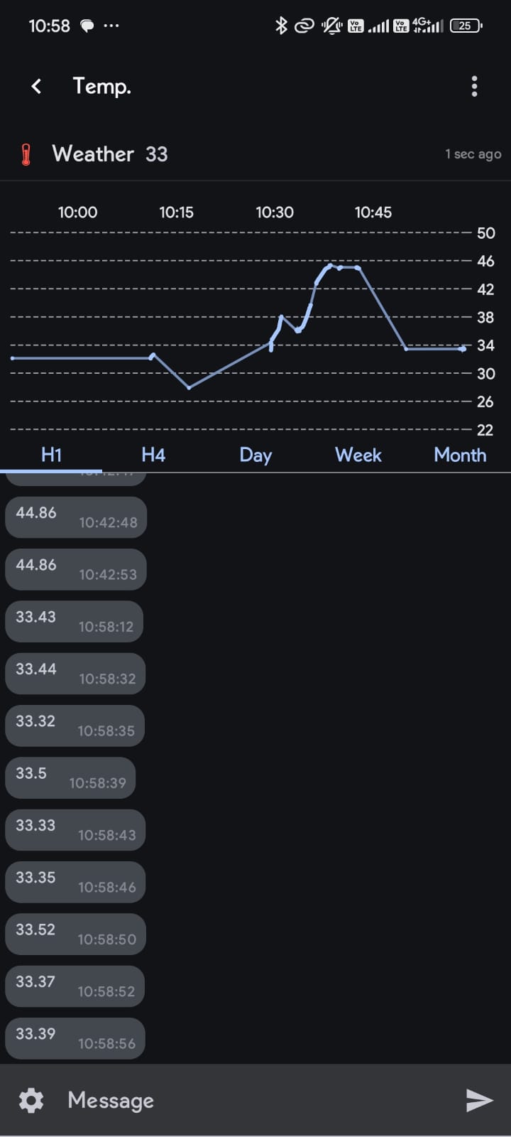
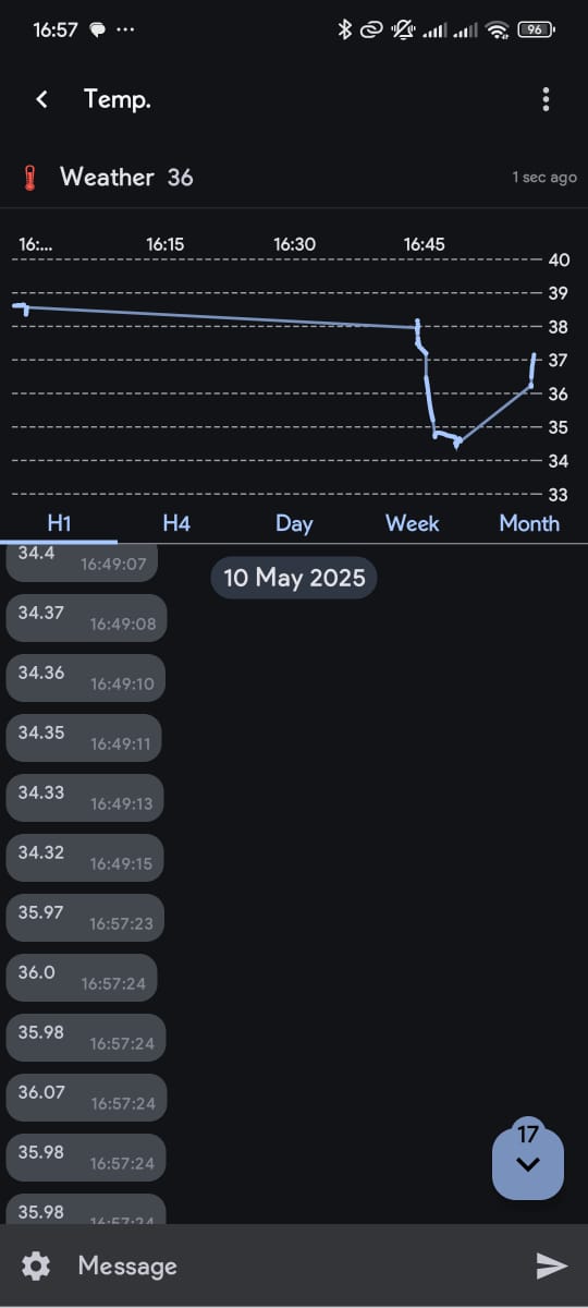
- Temperature Trends: We see the expected daily warming/cooling and the sensor's fine resolution (small ±0.02 °C noise).
- Location Impact: A significant peak spike up to ~46°C highlighted a major issue: the sensor wasn't measuring ambient air, but the heat from hot concrete it was initially placed on. Relocating helped mitigate this.
- Power Fluctuation Noise: Subtle temperature jitter was more apparent in the morning and evening, likely linked to power instability during low light/charging transitions.
Crucially, the data reporting frequency varied significantly based on light conditions:
- Morning (7 AM+): Starts slow (~15 min/message), increasing to ~5 min/message as sunlight intensifies.
- Mid-day (10 AM+): Becomes very frequent (almost every second) under full sun. Clouds cause it to drop back to 5-15 mins.
- Evening (After 5 PM): Frequency drops drastically (5-15 mins -> 30 mins), stopping completely after 6:30/7 PM as supercapacitors deplete without solar input.
This changing frequency is a direct indicator of the system reacting to available solar power and supercapacitor voltage. More light means more power, allowing the ESP32 to operate and transmit more often. Less light means less power, forcing it to slow down or eventually enter deep sleep until sufficient charge is regained.



Current Limitations & What's Next
While the project is operational and demonstrates the concept effectively, I've identified a few areas for improvement and future development:
-
Sensor Accuracy: The BME680 is sensitive to heat generated by the ESP32C3 itself, which can affect temperature and humidity readings if not properly isolated.
Future: Design an enclosure that physically separates the sensor from the main microcontroller board, ensuring better airflow around the sensor. -
Placement Heat: Initial tests showed that heat absorbed and radiated from the surface the device sits on (e.g., concrete) can significantly skew readings.
Solution: The device is now mounted on a wooden pole to minimize ground heat interference and improve air circulation. -
Power Efficiency: The current firmware isn't fully optimized for ultra-low power consumption, potentially draining the supercapacitors faster than ideal during prolonged low-light conditions.
Future: Implement aggressive ESP32C3 Deep Sleep modes, optimize WiFi connection/disconnection times, minimize active mode duration, and refine supercapacitor balancing for minimal quiescent current. -
Solar Charging Circuit: The current simple diode-based charging is functional but incurs a voltage drop.
Future: Explore more efficient solar charging ICs (e.g., MPPT controllers suitable for low power) to maximize energy harvesting and reduce losses.


